ROTARY PELLET LAUNCHER
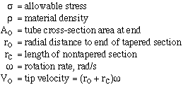
The rotary pellet launcher (RPL) is a heavy tube rapidly rotating so as to accelerate small pellets of rock. The tube consists of a straight, nontapered section near the end and an exponentially-tapering section inward toward the hub from the nontapered section (see fig. 5-31). The notation is:

The following equations define a design:


where a =  and erf is error function.
Now let
  There exist the following ratios,
given as functions of the dimensionless parameter a:


The mass ratio is the ratio of RPL tube mass to the mass of a tube of the same
density and equal length, with constant cross-sectional are
 .
Curves of the three ratios are plotted in figure 5-32.
Typical materials of interest for use in an RPL are given in table 5-23.
TABLE 5-23 (gif format)
| Material | e, g/cm^3 | Sy, 10^3 MPa |  , m/s , m/s |
|---|---|---|---|
| Maraging steel | 8.0 | 2.76 | 831 |
| E glass | 2.5 | 3.45 | 1663 |
| Carbon fiber | 1.4 | 2.76 | 1987 |
| S glass | 2.5 | 5.17 | 2036 |
| Kevlar-49 | 1.45 | 3.62 | 2237 |
| Fused silica | 2.2 | 13.80 | 3545 |
Here Sy is the yield strength in MPa;  is the critical
velocity,
  .
To build an RPL to eject pellets with velocity less than
  , the
launcher can be a straight tube of uniform cross section. But above
  ,
the RPL must be tapered for part of its length, increasing in thickness
toward the axis.
Note that  . Now consider a reference design. Let
 =
3965 m/s. The material is Kevlar, at 60 percent of yield strength, or
 =
2.2 GPa (315,000 1b/in.^2). Take the density at 1.55g/cm^3, or 7 percent
higher than the tabulated value. Also let
  = 83.6 cm^2, or a diameter of
approximately 10.3 cm at the tip; L = 15.2 m. Then:

Now consider the bending stresses due to acceleration of the pellets. Suppose pellets of 10 g mass are accelerated. Near the tip the imposed acceleration is some 100,000 g. The pellet presses on the side of the tube with a force of approximately 8.9 kN, which is denoted F. The associated stress at any distance r from the tip has maximum value at the outside of the tube. Let the tube diameter there be d; the stress a then is

and d^2 is proportional to A. A plot of a as a function of radial distance from the axis is given in figure 5-33. Note that for the reference design, the stress is maximum some 2.44m inward from the point where the tube ceases to taper. But even at that maximum, the stress is only some 7 percent of the yield stress for Kevlar. Stress relief may be provided by making the tube ellipsoidal in cross section.
The reference design is a rotating tube without counterweight. The lightest counterweight is not a solid block but is an exponentially tapering shape, like the tube. A double turret has a mass 17,340 kg. Two such turrets are needed, counterrotating, for the mass-catcher to maintain zero net angular momentum.
The catchers receive 40 kg/s at, say, 200 m/s for a force of some 8 kN.
To null out, some 2 kg/s are ejected at 4000 m/s. For the dual turrets
described approximately 200 pellets are ejected per second; each pellet
is 10 g. The theoretical power required is  ). If provided by a
space nuclear power system at 45 kg/kW this requires 7200 t.
To achieve thrust, the RPL must be made to release its pellets with approximate uniformity in direction. This may be accomplished with the pellet injector of figure 5-31. The feed tube rotates at the same rate as the RPL tube, pressing a pellet against the restraint. There is a hole in the restraint which lets a pellet through when the tubes are pointing in the right direction. A gate in the feed tube, controlled by a cam, ensures that only one pellet goes through at a time. Use of the gate means that the hole need not be small.
The RPL is subject to considerable wear due to friction and abrasion from the pellets, and must be designed for easy maintenance. This is accomplished by providing the tube with a removable liner, and by designing other high-wear parts for easy removal and replacement.