A section from a symmetric structural shell transmitting only normal stresses in orthogonal directions may be designed either as a stressed skin or a rib system. The stressed skin is the most efficient in that the same material carries the stress in both directions and there is integral resistance to secondary torsional and bending loads. In addition, both fabrication and construction generally are simplified and problems with sealing joints, finishing, and maintenance are reduced.
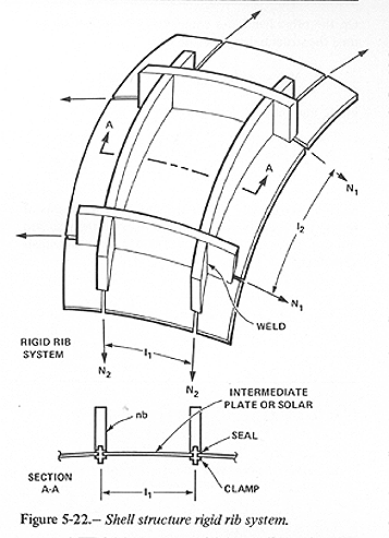
For a rib system, such as shown in figure 5-22,

each orthogonal set must
entirely carry the membrane force (Nl or N2) in that direction. This
increases the mass required to carry the membrane stresses by the factor
 refer to the membrane stresses
in directions 1 and 2) plus the intermediate plates required to bridge
between the ribs. Moreover, if the ribs are made of cable and are
flexible there is no resistance to secondary torsion, bending, or buckling. There may, however, be some advantages in fabrication and
construction to include some cables encased in the ribs.
The obvious requirement for any shell configuration is to avoid ribs whenever possible. Therefore, this design assumes a stressed skin structure except in the windows where the required ribs flare into the skin at the boundaries.
Design Formulas for Torus
For a stressed skin design of a torus the required skin thickness in the meridional and hoop directions, respectively, are given by
(1)

(2)

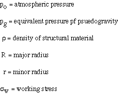
where
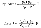
The analogous equations for the cylinder and sphere are

In general  for the range of values of interest in this design.
For the Stanford Torus,
 , R= 830m, and r= 65
m. (Note: Since angular velocity must be
  Furthermore, projected area
  .) The structural material
is assumed to be aluminum with
  = 2.7 t/m^3
and
  = 200 MPa (29,000
lb/in.2). The value used for
  is 7.66kPa (1601b/ft^2), which is 530,000
t of internal mass on a projected area of 678,000 m^2. For a tabulation of
internal mass, see tables 5-2 and
5-3.
The thickness required to contain both atmospheric pressure and internal mass is determined by equation (2):

Considering atmospheric pressure only, equation (1) governs:

This represents a difference in cross-sectional area of

An efficient way to use the structural material might be to construct the shell with the minimum thickness needed to withstand the atmospheric pressure, and provide the additional required area in the form of hoops incorporated into the supporting substructure of the internal structures, as illustrated in figure 5-23 (overleaf).
The structural mass for a torus design with a stressed skin is determined by

On the other hand, if a completely ribbed system were used the structural mass would be


Since approximately 1/3 of the surface area consists of solars (the chevron windows), the mass of the standard torus is taken as,
